In this case we are talking about plants using diathermic oil at temperatures up to 250-300° C and also 350° C. Diathermic oil at these high temperatures is very dangerous and potentially detrimental, and it is therefore necessary to avoid any risk of oil leakage.
A magnetic drive pump is a type of pump that employs a magnetic coupling between the motor shaft and the pressurized oil within the rotor of the pump. Thus eliminating any kind of mechanical coupling. For sure this is a choice that entails higher costs, but with no comparison on the perspective of safety that it ensures.
Mechanical seal pumps for high temperature oil do also exist, of course, and they are also very good performing pumps. But when temperatures involved rise over the 180° C, in Tempco we prefer to opt for magnetic drive pumps. Using a mechanical seal pump it’s indeed always possible that issues happen, due for example to a bad management of the pump or for air infiltration, that can lead to cavitation within the pump.
Choosing a magnetic drive pump thus completely avoid all the risks of oil leakage, due to the fact that it eliminates the presence of mechanical seals within the pumping circuit of the oil.
In fact the order came from an important constructor of anodic oxidation plants which operates on the US market through a local facility. The customer is realizing a plant for a main aircrafts manufacturer. For the thermostatation of the treatment tanks and the galvanic baths, the constructor decided during the project of the plant to substitute classic coil exchangers with TCOIL plates.
The final user has indeed the need to treat big parts and components, so that it was necessary to have the whole input section of the tanks available to insert the pieces. The solution using TCOIL plates offers the advantage to have a smaller and thinner thermal exchange system compared to bulky tube/coil exchangers.
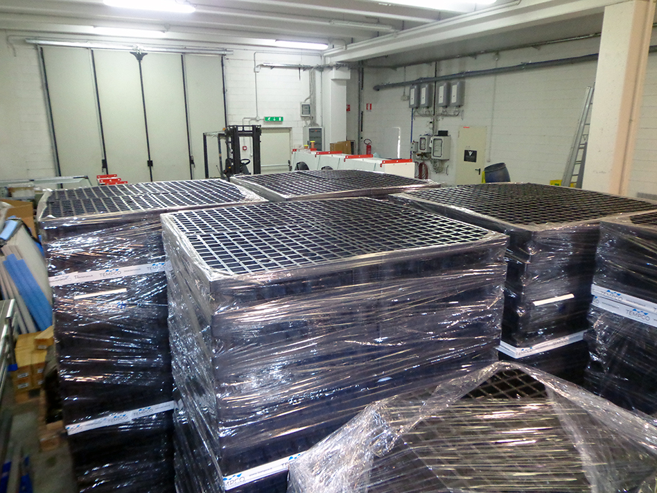
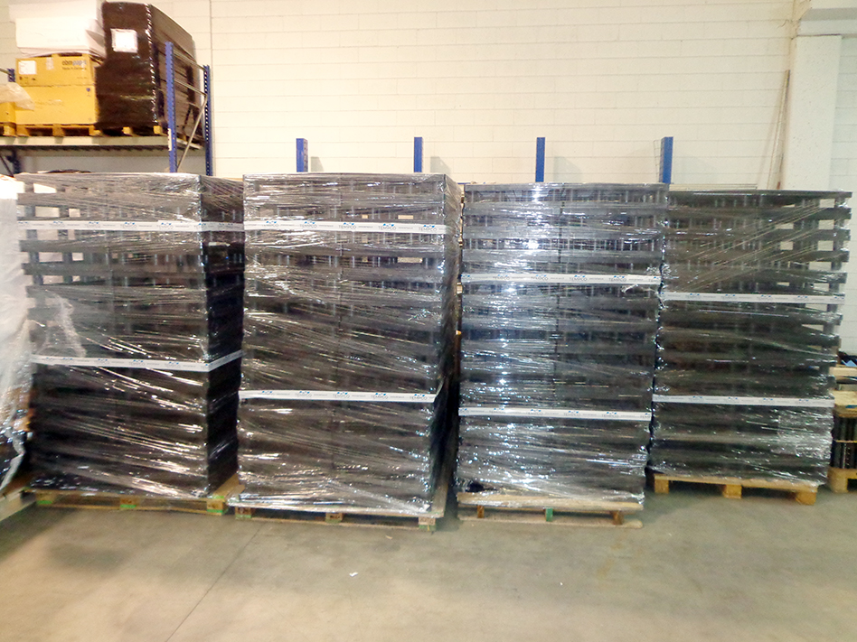
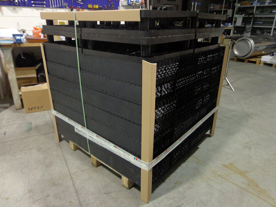
We’ve realized 20 TCOIL plates of different sizes, taking further advantage of the great flexibility typically offered by dimple jacket exchangers to adapt the thermostatation systems to existing and yet designed tanks. The plates are fed with over heated water for the heating step, while refrigerated water is employed for the cooling cycle.
Construction material is AISI 316L with augmented thickness, in order to ensure resistance to the harsh working environment in which the dimple jacket immersion exchangers are aimed to be used, in presence of sulphuric acid within the electro-galvanic baths.
The presence of Tempco’s thermostatation systems is becoming more and more distributed and widespread within the pharmaceutical industry. At the beginning of the summer, we have received a new order from a CDMO company (Contract development and manufacturing organization), which is a third-party company that develops and produces pharmaceuticals for big international corporations in the pharma sector.
The customer in this case is an important Italian Group that manufacturers APIs, which has selected our solutions for the fine regulation of recipes temperatures employed in reactors.
A rack of cryogenic tubes (for deep freezing of cells). White space on tubes left free for your copy.
The supply contract involves a complete set of plate heat exchangers, thermal exchange systems in a special version for API production with nickel brazing and ensuring mechanical resistance for pressure pulsations and impact pressure, aimed for temperature regulation of reactors employed in the laboratories.
Which cooling system is the better choice to obtain cooling water for production processes, among chillers, evaporative towers or dry coolers, is a very often requested topic. The choice depends first of all on the temperature level of the water required. Clearly, if water at 10° C is needed, or even at 0° C or under zero, the only way to go is a refrigerating group, or chiller.
But there are several halfway situations too, where cooling water required has slightly higher temperature levels, such as 20-25 or 30° C. Which still is cold water, but it can be obtained leveraging other kind of cooling systems. Each one offering its benefits and disadvantages, clearly.
The refrigerating group is the one that is less affected by climatic conditions, if properly designed. There are also chillers tropicalized, able to operate also at high ambient temperatures, and with to special equipments enabling operations as well during the winter season. We’re talking here about EC fans, that provide the adaptation of the condensation speed.
When cooling water is required at temperatures of 25-30° C, that’s when the doubts start, if it’s better choosing a chiller, an evaporative tower or a dry cooler. It all depends on the climatic conditions. An evaporative tower employed at latitudes typical of North or Central Italy, and Europe, allows to obtain cold water at a temperature of approximately 29-30 or 31° C. Here, a dry cooler struggles, just because it’s cooling work depend strictly upon the ambient temperature. So that during the summer season, when temperatures reach 30-35° C, it will be possibile to obtain cooled water at temperatures 5° C higher, and so that means water at 35-40° C. Furthermore, it’s true that during the winter season, or the mid-season, a dry cooler allows to have cold water at the required temperature.
In the comparison between a cooling tower and a dry cooler, the first one has the advantage to have an open circuit of the water, while dry coolers employ a closed circuit, with impacts on the performances. On the other side, having a closed circuit of the water means that there are no side effects caused by dust present in the external air, nor evaporation or water consumption, avoiding the need of refilling treated water.
However, with water in a closed circuit there is the risk of freezing during the winter, that could cause breaks on pipes, and thus requiring the employ of glicol.
It’s overall a complex theme, and the right solution has to be carefully evaluated case by case. A trend ongoing lately is to combine chillers with dry coolers, that during the winter season can easily replace the operations of the chiller, allowing to switch-off the compressors. With significant gains in terms of energy savings. The same dry cooling systems can be achieved using an evaporative tower, but taking care of interposing a heat exchanger, because the open circuit of the tower exposes water to contamination, and therefore cooled water should be treated prior to feed the industrial production process.
Hydrogen and fuel cells foster a great opportunity for the deployment of sustainable and clean mobility of future, alternative to electric vehicles. For a project related to a hydrogen truck, we are supplying in several steps a series of brazed plate exchangers, completely manufactured in stainless steel.
The heat exchangers are employed on the hydrogen vehicle to transfer the heat from the cooling circuit of the fuel cell to the main cooling circuit of the vehicle, in order to maintain the two cooling circuits separated.
These are in fact heat exchangers of the same version as common brazed plate heat exchangers, but instead of copper they are completely made in using stainless steel.
The project started one year ago and required a series of sizings and technical refinings, in order to define the model of heat exchangers to be supplied. As usual in these kind of brazed plate heat exchangers, and even more in this particular case, the exchangers have been pressure tested and also passed destructive testing, in order to ensure maximum reliability of the thermal transfer equipments.
Previous videos focused on anodic oxidation applications triggered some questions, mostly referred to the selection of corrosion resistant materials in heat exchangers. In fact, heat exchangers employed in anodic oxidation have to work with solutions of sulphuric acid with 20% concentration, at temperatures of approx 20-25° C. Based on ISO-corrosion diagrams, these conditions would suggest the use of AISI 316. But the risk in these kind of plants is that the temperature goes even higher, for example during the shut down of the plants during the summer season.
Another kind of material must then be selected, being the Avesta 254 SMO, a high-performing alloy which offers excellent corrosion resistance even at high concentrations of suplhuric acid and temperature levels. In case it’s not enough, it is also possible to use Titanium, commonly employed with seawater applications thanks to its excellent resistance to high concentrations of chlorides and high temperatures.
Talking about costs, if AISI 316 represents 100, for both Avesta 254 SMO and Titanium the cost is about 200, depending on variations on the market.
When sulphuric acid concentration gets higher the problem gets more complicated, and Avesta and titanium are no more suitable. It is therefore necessary to use Hastelloy C276, another high-performing alloy with a quite high cost and with relatively low availability on the market. Anyway, this is a kind of material that can be cold-printed, and so a perfect solution for plates in heat exchangers.
The options are quite similar in case of shell and tube exchangers, being it possible to find on the market tubes in Avesta 254 SMO, and also titanium pipes even if it can be a little more difficult, as well as for Hastelloy C276. But there are also other materials that can be employed here, such as Incoloy and Monel. These are anyway more sophisticated materials, involving higher costs both for the raw material and the working process.
When the corrosion level goes even higher, it’s also possible to use graphite exchangers. These are exchangers with a peculiar construction, in some way similar to plate and shell and tube exchangers, made using mixtures of graphite.
Moreover there are plastic exchangers, in particular U tube bundle exchangers consisting in an ensemble of tiny plastic tubes to be immersed inside the tank to be thermoregulated. Usually these are made using polypropylene or PVC or other plastic materials, depending on the kind of application, workability and the temperature levels. Involving heating tasks, in fact, using plastic always requires great attention.
Finally, leaving the anodic oxidation field and entering the pharma sector, talking about resistance of materials using corrosive fluids there are also exchangers and reactors made with glass. Anyway, this is a completely different industrial production environment, with very different levels of accuracy and much more delicate than more ‘heavy’ anodic oxidation plants.
The ‘magic word’ is non-clogging filling packs on cooling towers. A long-term customer of Tempco, with several textile facilities around Europe and an important installed park of evaporative towers, launched a few years ago an intervention to increase performances and efficiency on operational costs of these machinery.
Some year ago we did a complete analysis of critical issues involving plants using evaporative towers, installed in a couple of industrial production facilities. In collaboration with an engineering and design studio, we made it clear that the rapid and excessive clogging of the filling packs within the towers generated a decrease of their cooling capacity, combined with a gradual increase of power consumption.
The technical office then agreed on testing a tower equipped with a non-clogging filling pack, different from a splash type one, obtaining quite good results that convinced them to adopt this solution as a standard for all of the plants, first equipment cooling towers but also for the revamping of existing ones.
Now following an annual maintenance and integration program, the customer is gradually substituting all of the filling pack systems of its towers, even if it requires bigger machines, and therefore a higher first investment cost, but with a two-seasons long ROI, achieving a strong decrease on maintenance and energy consumption costs.
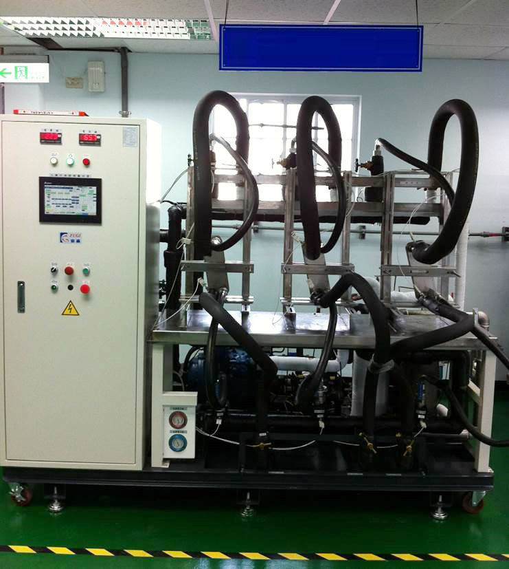
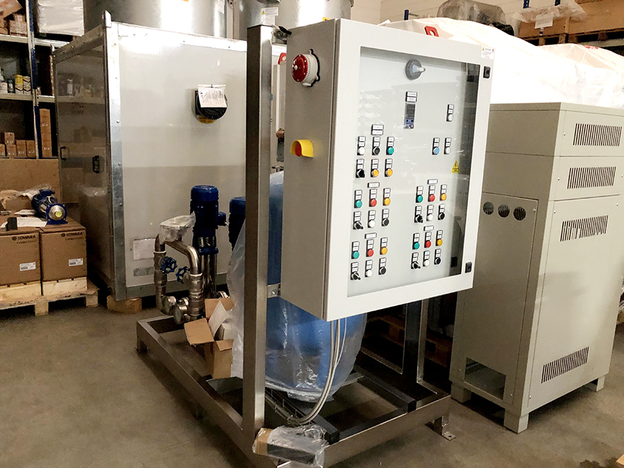
Mono fluid thermoregulation systems are gaining more and more ground within the pharmaceutical sector, for the precise temperature regulation of reactors. These solutions allow to achieve the chemical reactions required for the production of active principal ingredients, for example, carefully following production recipes that require a defined thermal program.
Mono fluid thermoregulation units are therefore systems that, if properly programmed, allow to follow the thermal scheme of a reactor or a chemical equipment. The units allow to monitor, control and regulate temperatures of the product inside the reactor. Mono fluid thermoregulation employs a circulating pump, ensuring the flow of the fluid between the jacket of the reactor, or the half pipe of the equipment, and an array of heat exchangers, or electrical heaters. The whole system is managed by an electronic regulator that controls the temperature of the fluid.
On the secondary circuit it is possible to have vapour, employed to heat the fluid, and refrigerated water or cooling tower water for the cooling of it. If vapour is not available, a heating section can be employed using electrical resistors, managed as well by the electronic regulator.
The system can be managed by remote using a PLC, an electronic regulator or other interfaces. It is then possible to control a quite varied range of temperatures, starting from under zero temperatures down to -30°, going up to very high temperatures, reaching also 250° C. Depending on the range of temperature required, the fluid employed will be simple water, or glicol water with anti-freeze to reach low temperatures. Pressurized water, over-heated, is employed to reach temperatures up to 140° C, and finally diathermic oils or silicone oils are employed for high temperatures.
Diathermic oil is usually employed for plants involving only high temperatures, while silicone oil, or synthetic oil, is used in plants requiring a wide range of temperature regulation, from under zero up to very high temperatures. These oils have indeed the characteristic of having a good flowing property at low temperatures, and also offer good thermodynamic and physic properties at very high temperatures.
These units can be provided compliant to several regulations, depending on the kind of application or the Country of installation. Taking about chemical and pharmaceutical industry, it will very common to be in presence of an explosion risk environment, thus requiring an Atex execution. If the units are for installation within the United States these will be compliant with UL regulations, while if the destination is Russia they will be provided with EAC certification.
Very often mono fluid thermoregulating units have to be combined with dedicated refrigerating groups, not directly integrated within the unit in order to ensure production continuity in case for example of a fault in the cooling section. This kind of thermoregulation systems must indeed be conceived to ensure maximum flexibility, maximum reliability and extreme precision in temperature control.
We collaborate since approximately 10 years with a customer that operates in the lead-acid batteries recycling, providing special cooling systems employed on the burners within the plants, aimed to the recovery of materials.
These systems present a quite typical composition, which includes:
self-draining dry cooler functioning with only water
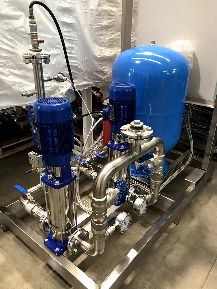
pumping group with 2 redundant pumps
monitoring and managing panel
A peculiar characteristic of the solution is the redundancy of equipments, due to the fact that for this kind of application, requiring extreme operating conditions and working constantly 24/7 during 365 days per year, it’s absolutely necessary to always ensure the availability of the cooling process.
The presence of lead-acids also eventually creates a very harsh and aggressive working environment, and therefore another characteristic is the employ of stainless steel materials for the construction of the instruments.