Brazed plate heat exchangers (BPHE) for high temperatures are a key asset in two main and emerging applications within the ecological transition, being it CO2 refrigeration and fuel cells using hydrogen as a renewable power source. Two renewable sources that are crucial for sustainability and to contrast the effects of climate change in power generation and industrial refrigeration.
CO2 employed as a natural refrigerant gas (R-744) is an excellent alternative to traditional synthetic refrigerants (CFD and HCFC), offering a 0 value of Ozone depletion potential (ODP) and a GWP (Global warming potential) of about 1, far less than that of traditional refrigerants. CO2 has also a very high thermal transfer coeffient, much higher than synthetic refrigerants, is stable and non-toxic, but has to work at very high pressure levels, thus requiring higher standards for the design of refrigeration systems and components. Otherwise, its excellent flow performances allow to significantly reduce the size of compressors and refrigeration equipments, making the overall system more compact.
Furthermore, CO2 is a natural working medium of easy access in the environment, and is also a by-product of many industrial processes and factories, so that refrigeration using CO2 represents an excellent solution for the recovery and recycling of exhaust gas.
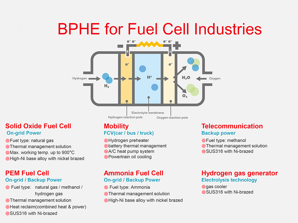
Another very important application for high temperature brazed plate exchangers involves fuel cells, using hydrogen which is a optimal candidate for energy of the future as alternative to fossil fuels. Fuel cells are zero emission power generation systems that employ an electrochemical process to obtain electricity and heat from the chemical reaction between hydrogen and oxygen, generating water as by-product. Therefore a totally green and clean power generation solution.
Nowadays there are several and different fuel cells technologies deployed, and brazed plate exchangers are employed in a series of tasks such as pre-heating of air and fuel, cooling of the cell and humidity and vapour management, through energy recovery of the generated heat. All of these applications have in common high temperatures requirements, as well as high corrosion resistance.
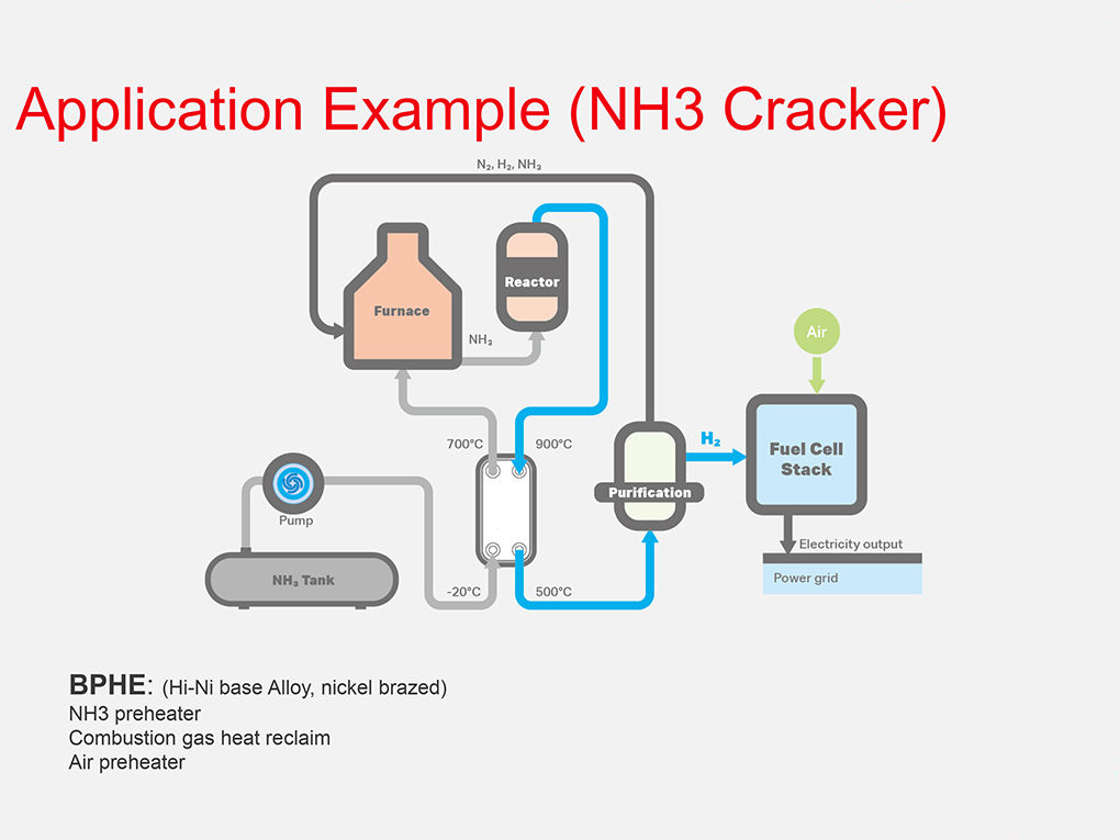
In the schemes below, there is a series of examples of brazed plate exchangers applications in different fuel cell related technologies, used in micro-grids, sustainable mobility and for hydrogen production.
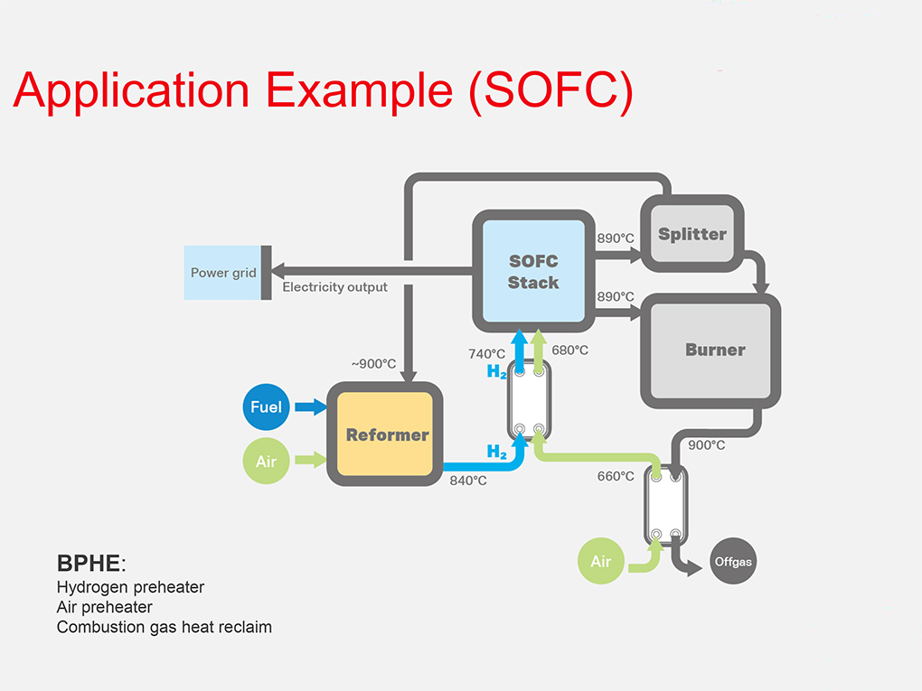
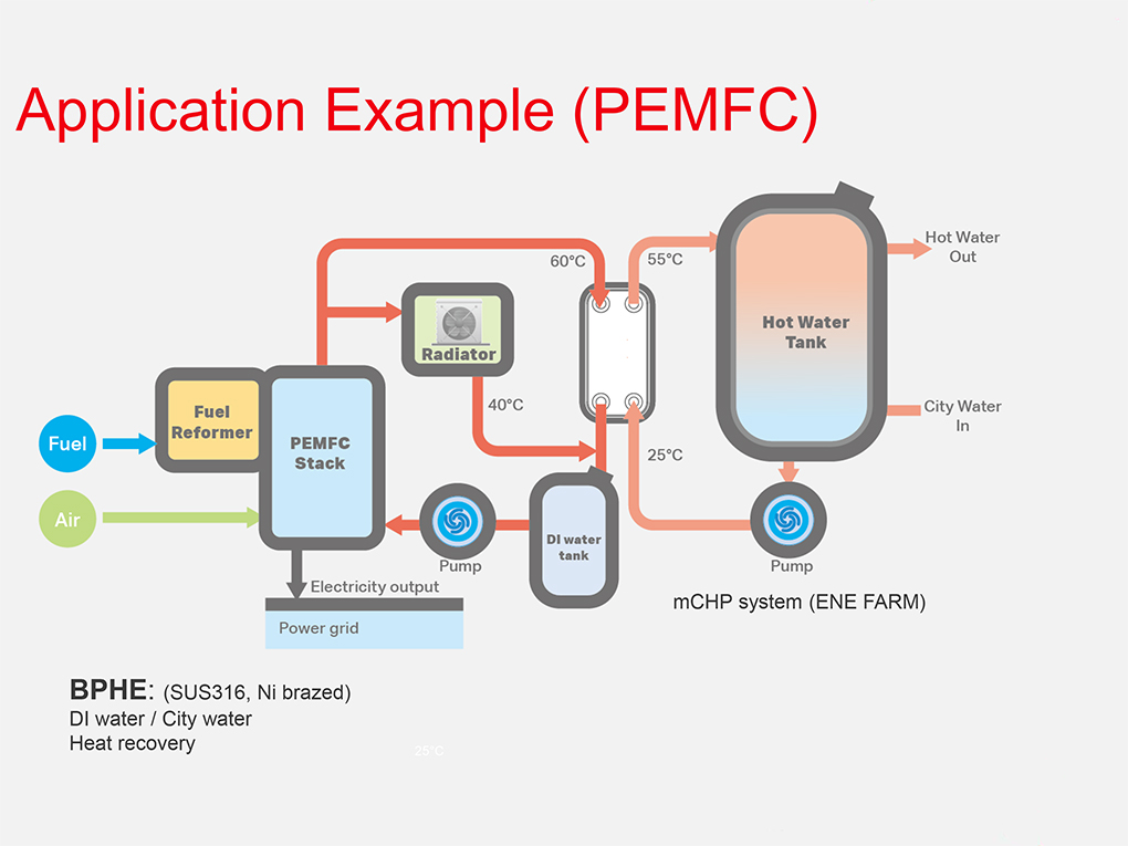
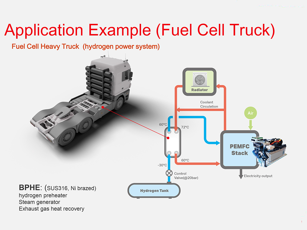
Among them there are Solid oxide fuel cells (SOFC) employing exchangers for air pre-heating and heat recovery of thermal energy generated by the oxidation process of hydrogen. In Proton-exchange membrane fuel cells (PEMFC), high temperature brazed plate exchangers are used for heat recovery aimed for water heating. Brazed plate exchangers provide hydrogen pret-heating and exhaust gas heat recovery in trucks using fuel cells, making heavy-transportation sustainable. Finally, brazed plate exchangers are used for ammonia pre-heating in NH3 cracker systems, employed for hydrogen production from NH3 molecules.
Stay updated on the latest applications by subscribing our monthly Tempco Newsletter – Solid Temperature.