How to handle plate heat exchangers when using them with steam? In case of plate heat exchangers that can be inspected there are no problems, because it’s always possible to maintain and repair them. In case of hammering pressures, steam peaks or condensate that damages the gaskets, it’s indeed possible to open the exchanger, replace the gaskets, closing the exchanger and make a pressure test, and the heat exchanger is ready back to work. A different story with brazed plate exchangers, that cannot be repaired when they get broken.
The main problem with plate heat exchangers using steam happen when there is not a proper condensate discharge, so that condensate remains inside the exchanger. When new steam enters the exchanger in presence of stagnant condensate, the condensate suddenly evaporates and noises such as clicks and cracks can be heard. These are caused by the sudden evaporation of the condensate which leads to very high pressure peaks, that can damage the exchanger irreparably.
An efficient condensate discharge must then be installed, ensuring that the discharge pipeline have no counter pressures, in order to achieve a complete draining. A vacuum breaker valve should be installed as well, on the outlet circuit of the steam regulating valve, working in fact as a backwards restraint valve: when the steam flow stops, the vacuum breaker valve opens letting air in, ensuring the complete draining of the exchanger, forcing air and condensate out of it through the condensate discharge.
An information we are often asked for is the size of hydraulic passages in plate heat exchangers, especially when working with dirty fluids or with particles in suspension.
The actual trend is to decrease the size of passages, in order to obtain a higher turbulence of fluids, even when working with low flow rates, therefore obtaining a more packed transfer network with multiple crossings and angles. The reason of it is to increase the thermal transfer rate, decreasing the required thermal exchange surface for a certain thermal duty, producing smaller and more efficient exchangers, with lower costs and more competitive.
But there are some limits, obviously, because when working with dirty waste water, a small passage can be clogged very quickly. And working in industrial applications, it happens very often, working with not very clean water, some times in open circuit, or even in closed circuits but polluted by the production processes that they serve.
Brazed plate exchangers have passage of approx. 2 mm, which is a very small section. But brazed plate exchangers are conceived ad maintenance-free exchangers, except for chemical washing, the so called cleaning-in-place, which is possible only if the exchanger is not completely clogged.
Plate heat exchangers that can be inspected have instead a variety of passage sections, based on the thermal design of the exchanger. For example, in our Tempco range of heat exchangers the average section starts from 2,5 mm and goes up to 4 mm, for applications with very dirty fluids or requiring very contained pressure drops. It is also true that pressure drops can be piloted choosing a proper Chevron angle of the plates, and having a larger passage expands the application range of the plate exchangers.
There is also a particular type of plate heat exchangers, called free-flow exchangers, which have no contact points and very large passages. These exchangers are employed in particular production processes, such as paper mill or the food production of fruit juices with big pulp particles in suspension, that could clog a traditional plate heat exchanger very quickly.
Free-flow heat exchangers have very large passages, that can measure 6 mm or even 12 mm. These exchangers don’t exist in all the possible sizes and design plates, and not having contact point they offer a lower resistance to pressure gaps compared to traditional exchangers. In addition, plates have to be constructed with higher thickness, involving higher costs.
How to select the kind of passage in a plate heat exchanger, at last? The selection is clearly based on the kind of application, which defines the type of plates, the size of passages and the depth of the plate corrugation.
– head/bottom recovery on distillation columns
– head condensing on distillation column
– bottom cooling of the distillate
– bottom distillate reboiler
– pre-heating on column feeding
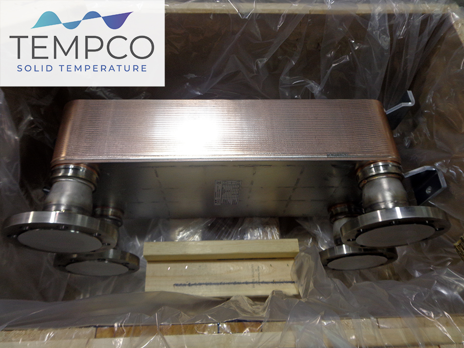
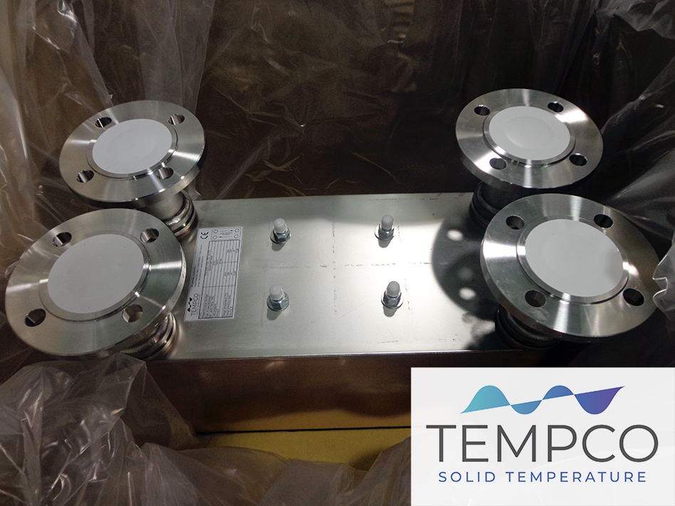
These are some typical applications in distillation/condensation chemistry plants. In this case the customer chose this solution to have compact sizes and high thermal transfer efficiency, pushing all the phases of the process aiming to limit energy consumption.
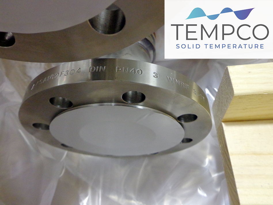
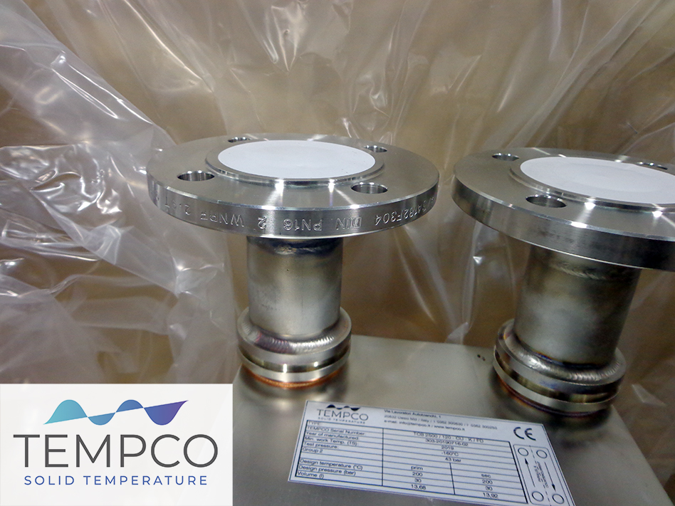
Based on thermal duties involved, the brazed exchangers are installed in multiple units in parallel configuration. The brazed exchangers employed are heat exchangers of the TCB3100 and TCB4100 series with flanged dn100 and dn80 connections, which allow to manage processes with very high flow rates.
During the head/bottom recovery on distillation columns we’ve implemented an energy recovery concept, in fact achieving a thermal exchange between the final product and the product entering the distillation column. Is therefore possible to leverage the final product temperatures for pre-heating the incoming product, further increasing the overall process efficiency.
To fulfill the cycle we’ve also supplied two small plate coolers of the TCB H series for high temperatures, aimed to manage a cooling cycle with a thermal gap between the primary and secondary circuit exceeding 160° C.
Evaporative towers are thermal machines employed for water cooling in industrial production processes, for outdoor installation. Very often in Tempco we did applications in geographical areas with extreme climate conditions, with wide thermal excursions and therefore hot summers and very cold winters. We’re speaking of applications such as steel industries, in areas where temperatures go widely down 0° C, even at temperatures of -20° C, -30° C or -40° C. Aimed to serve industrial production processes, cooling towers must always ensure the best performances in every condition. That’s why they are designed and built upon the worst possible conditions, meaning the hot season as they are intended to produce cold water.
In order to ensure the proper functioning during the winter season, the main issue is represented by the temperatures going down to very extreme temperature levels. There are some tricks that are employed in these cases, the first being the employ of anti freeze resistances to maintain a certain minimum temperature of the water inside the tank, preventing it to freeze in case the tower gets arrested.
In fact, while the plant and the tower are working, water continually comes from the production process at temperatures of 30-40° C, and circulating within the tower it’s difficult for it to freeze. But it could occur that the process gets stopped, or the tower must be shut down for maintenance, or even due to vacation periods. The water inside the tank could then freeze.
When having big sized tanks, the anti freeze resistances are no more enough. An expedient is to insert some steam pipings, draining exhaust steam inside the tank coming from secondary processes, with an operation called ‘barbotage’. Further tricks are referred to the circulation of the water within the tower: as far as the temperature goes down, fans can be stopped, because the thermal transfer efficiency required decreases. Fans can then be stopped, or in case of EC fans equipped with inverters it’s possible to slow down the speed up to the complete arrest of the fans, as long as the natural ‘chimney effect’ of the tower will be enough to cool the water.
The more the water temperature goes down, the more the ‘chimney effect’ becomes exceeding, also for the thermal duties on the outlet of the tower. The next step is to stop the water from passing through the tower and directly bypassing it to the tank, in order to avoid that the water freezes inside the filling packs, clogging the tower. And also avoiding them to get heavy, with the severe risk they collapse inside the tower.
In case of prolonged cold temperatures, bulkheads can be installed to close the air inlet, limiting the air incoming which could freeze the water passing through or percolating from filling packs.
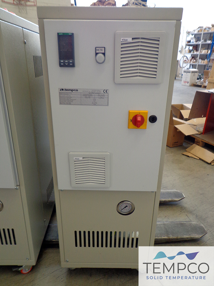
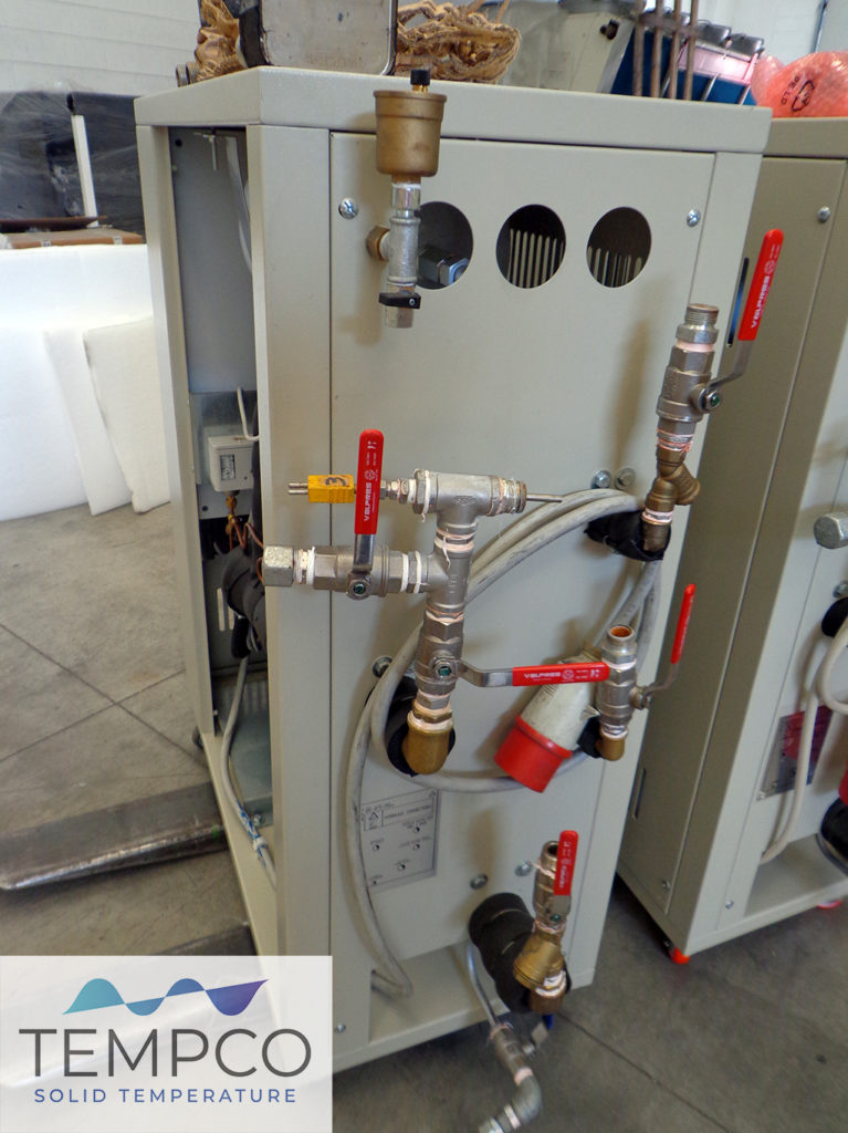
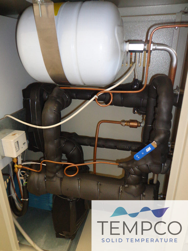
These pictures are showing thermoregulating units we developed for an automotive components supplier, also specializing in the sector of electrification and electric powertrain.
The customer needed thermoregulating units for application in test chambers of several automotive accessories and systems. The units are in particular going to be employed for testing of automotive components such as hydraulic power steering pumps, accessory systems for conditioning and sensors.
The test bench thermoregulating units allow to fulfill testing activities in a wide range of temperatures from -30° C up to +130° C.
Absorption chillers are thermal machines that allows to obtain cold from heat.
This special kind of chillers are usually machines of a high power capacity, employed in conditioning plants or industrial plants with significant thermal duties, and most of all constantly present. That’s because these machines employ a delicate thermal cycle. The application are mostly in the HVAC sector, both for residential and industrial conditioning.
But there are also machines with lower power capacities on the market, allowing to operate both in conditioning and production processes applications, being able to reach temperatures of -10° C.
Those are machines produced by Robur, and Italian company that acquired many years ago the patent of this technology from an American company. These are in fact small size absorption refrigerators. The standard range of these machines employs a direct fired burner which provides the heat required to trigger the thermal cycle for cold production.
A very interesting and smart idea that fascinated me is to leverage waste heat coming from industrial production to start that same thermal cycle. The company has in fact modified its machines to integrate a sort of heat exchanger, which allows to work using waste heat coming from industrial processes, waste steam or diathermic oil at the end of a process.
The interesting thing is the extension of an energy recovery approach for the production of cold, leveraging energy that otherwise should be lost and dissipated.
The only limit I see here is that this application requires waste heat at very high temperature levels, between 190° C and 220° C. And it’s not easy to find waste heat at this temperature, but in case it is available the solution becomes surely extremely interesting and intriguing.
I’m thinking about applications where there is a continuous generation of waste heat, allowing the continuous production of cold. A kind of solution that could then be very interesting in a wide variety of applications, such as on waste fumes from cogeneration plants, or fumes coming from steel industries of metallurgy plants, where high amounts of high quality energy is available, meaning high temperature waste heat.
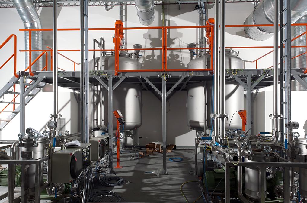
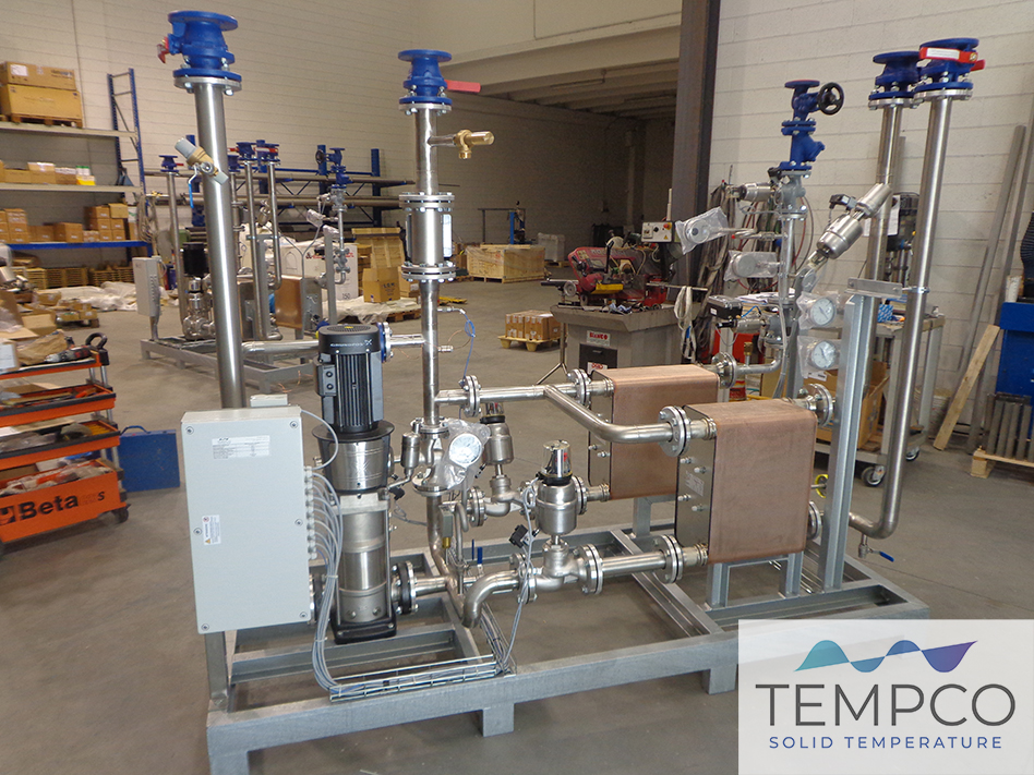
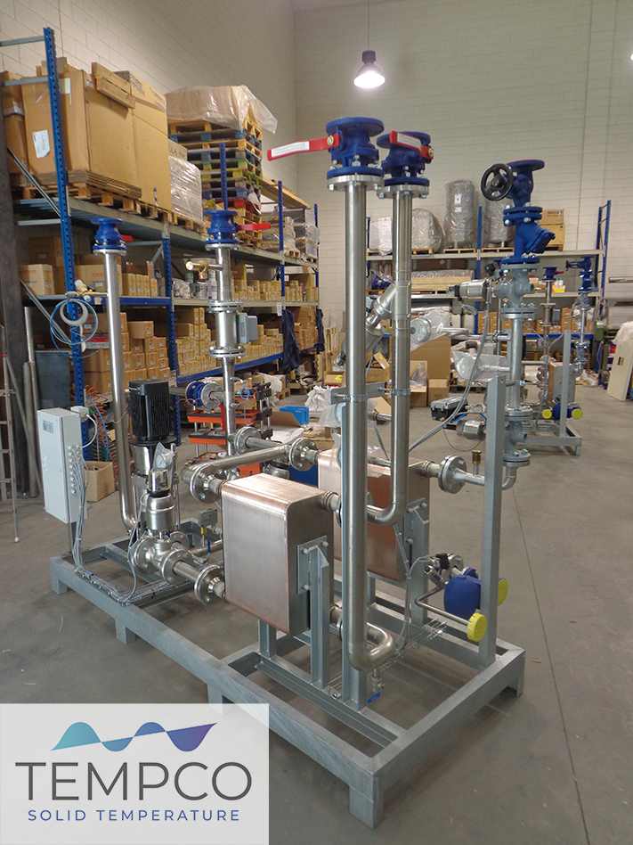
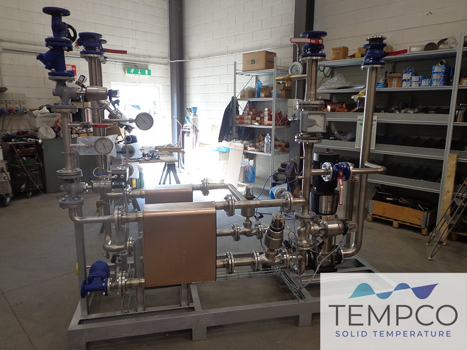
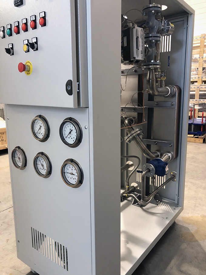
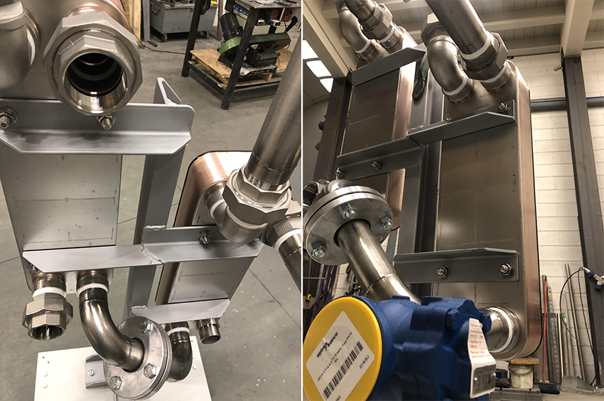
The images in this post are referred to thermoregulating units for the reactors in a new plant for concentration and refining of a customer which works in the chemical industry.
These units provide the accurate and fine thermoregulation within the production processes, with the particularity that they work using pressurized water at 150°C. It means that the application involves really demanding and stressing operating conditions, on all the components of the units.
It is made clear by the fact that these thermoregulating units required 6 years of R&D in Tempco, in order to select the right materials and components thanks to a series of tests and trials.
Energy management and energy saving within the temperature regulation in industrial processes. Not sure a new argument, but highly relevant in the field where Tempco operates, which I like to call ‘Second level energy’. What I mean is that we are not into primary power generation, but committed in how energy is converted and employed in process industry, and thus how thermal energy is transferred in thermal processes.
In Tempco’s activities, aimed to temperature control in production processes, energy is employed to power pumps’ motors, chiller compressors, fans drives and heating resistances, in case of heating equipments for diathermic oil and pressurized water.
I was thinking for a long time about solutions enabling a fine monitoring of the energy and efficiency of equipments. Then Industry 4.0 and IoT have become very popular ultimately, and in Tempco we are offering since more than a year a solution, called iTempco, that enables the remote real-time monitoring of our thermoregulating units installed at our customer’s facilities.
To be honest, this is not an easy success solution. Or at least, there is many speaking and curiosity about it, but at the end the application is made only by few customers. That’s because our temperature control machinery are utilities, not directly connected to the core production line of a customer. Therefore, customers are more willing to install condition monitoring on core production lines, while utilities remains in the background.
But from our personal point of view, thermoregulating units and temperature control equipments have power consumptions, thus impacting the final cost of the product. It is then useful to control also the functioning and efficiency of these thermal machines.
The monitoring is achieved thanks to interfaces that today are quite common, able to gather and interpret the signals of the units, transferring them online and storing data on cloud.
The first goal is to monitor the temperature levels, pressure and flow rates, to ensure the overall efficiency of the equipment. It is then possible to control the employ of the thermoregulating unit and to offer predictive maintenance services, or preventive maintenance as well. Or even more simply, when a customer calls to report a problem, the monitoring solution allows to know immediately where the problem is and suddenly make the right intervention, or also to instruct the customer on what to do in order to get the machine back at work.
Usually we implement the monitoring of electrical energy consumes. It is then possibile to have insights on the effective power consumption levels of a thermoregulating unit, as well as the consumption peaks, all related to the different steps of the production process but also to the seasonal conditions. Many times we’ve talked about how performances of machines, such as Cooling towers and Free coolers, vary depending on the different seasons.
Having a clear insight of the power consumption of a thermoregulating unit is very useful not only to optimize the engineering of the machinery, and properly calculating the power capacity to be installed, saving on initial investment and furthermore during its functioning. But it also allows to evaluate if it’s worth or not to implement inverters, thyristors and power modulating systems.
This is our first Tempco TREG HCST thermoregulating unit with EAC Certification (EurAsian Conformity mark) ready to be installed in a pharma plant for a customer in Russia. During the last months we started new investments in order to seize new interesting opportunities that are emerging in the Russian market.
We’ve launched last March the procedures required to obtain the EAC Certification for our TREG units, and their related accessories, aiming to export and install our thermoregulating solutions in Russia and the EEU Countries (Eurasian Economic Union). The EAC Certification was eventually achieved last May, in full lockdown period…
Let’s focus on another green and environmental aspect of evaporative towers, related to the cleaning of the water and issues coming from legionnaires. The Legionella problem has been widely explained, and mostly very clearly, but the theme of pathogen agents we’re exposed to has turned out being very up to date with the coronavirus outspread we’re going through.
All of the cooling towers nowadays on the market are equipped with all the precautions aimed to make them, let’s say, legionella-free. They are in other words equipped with self-draining basins and don’t have any stagnation spots for the water, that otherwise can cause dangerous bacteria to gather. Cooling towers today are also supplied with dosing systems of chemical additives, aimed to eliminate bacteria and algae, but also to maintain calcium carbonates in suspension avoiding scaling and clogging of the tower, and therefore ensuring the water is always clean.
All the evaporative towers on the market, or installed within the last five years, are thus provided with all the equipments that make them compliant to anti-legionnaires regulations. In case a cooling tower older is installed in your plant from more than five years, you can always ask for the intervention of specialized technicians, as our Tempco service assistants can be, but also your responsible for the water chemical treatments is surely aware of everything that must be done to face the legionnaires issue.
Comments Off on Anti-legionnaires equipments in evaporative towers
About
TEMPCO researches and develops systems and solutions for cooling, heating, control temperature and heat exchange in different industrial processes.