We gladly host a contribution from Robur, an Italian company based in the province of Bergamo, specialized in heating and cooling systems with low carbon footprint. In particular, the following article is about absorption chillers with energy recovery from high temperature waste heat in industrial processes.
Thermal energy is a very common presence in industrial production. Heat is indeed required in a number of production processes in industries such as food, industrial, textile, glass and ceramic industry, chemical, oil & gas and metallurgy.
Many among these industrial processes involve waste materials, and thermal energy is one that gets often lost at the end of the process. This is usually referred to as waste heat, and it can be present in several forms: fumes coming from furnaces combustion, or from internal combustion engines, turbine’s or cogenerators exhausts, steam coming from heat treatment plants or from drying tasks, just to name a few.
Within these same production processes, in a different step of the production line, a cooling system is then often required, also employing thermal energy but with a negative value, meaning a need for thermal cooling.
All these cases are suitable for the application of equipments that enable to employ that same waste heat to obtain chilling power, without further expenses in terms of primary energy consumes, by mean of heat recovery of the waste energy.
Waste heat can be divided in three classes: high energy, exceeding 650° C, mid temperature, between 225° C and 650° C, and low temperature, up to 225° C.
High and mid temperature waste heat are the most useful and ‘precious’, because they can be employed both directly or to feed further machinery such as cogenerators (combined production of heat and power) and absorbers, aimed to the production of chilling power. Low temperature waste heat can thus be employed in the form of hot air or water for heating purposes or pre-heating of further production processes that require low temperatures.
Cold production from mid-high temperature waste heat
The essential components of a machinery for cold production from waste heat are basically:
– waste heat at temperature higher than 220°C, with a proper flow rate
– heat exchangers, to achieve the thermal transfer from waste heat (such as exhaust fumes of a furnace) to a thermal fluid (diathermic oil or pressurized water)
– a circulating circuit for the distribution of the thermal transfer fluid to the absorber
– an indirect fired absorber for cold production
The overall system only require additional power for the operations of accessory equipments, such as circulating pumps and fans.
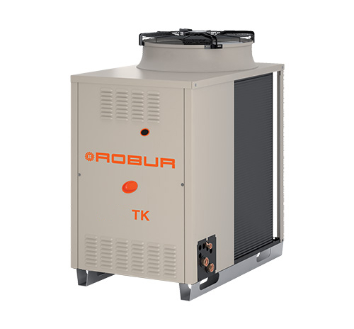
Power Fluid absorber units by Robur
Robur Power Fluid absorber units are an example of efficient thermal machines that allow to ‘produce cold’ leveraging the thermal heat coming from a technological process. The working cycle of the units is showed in this scheme.
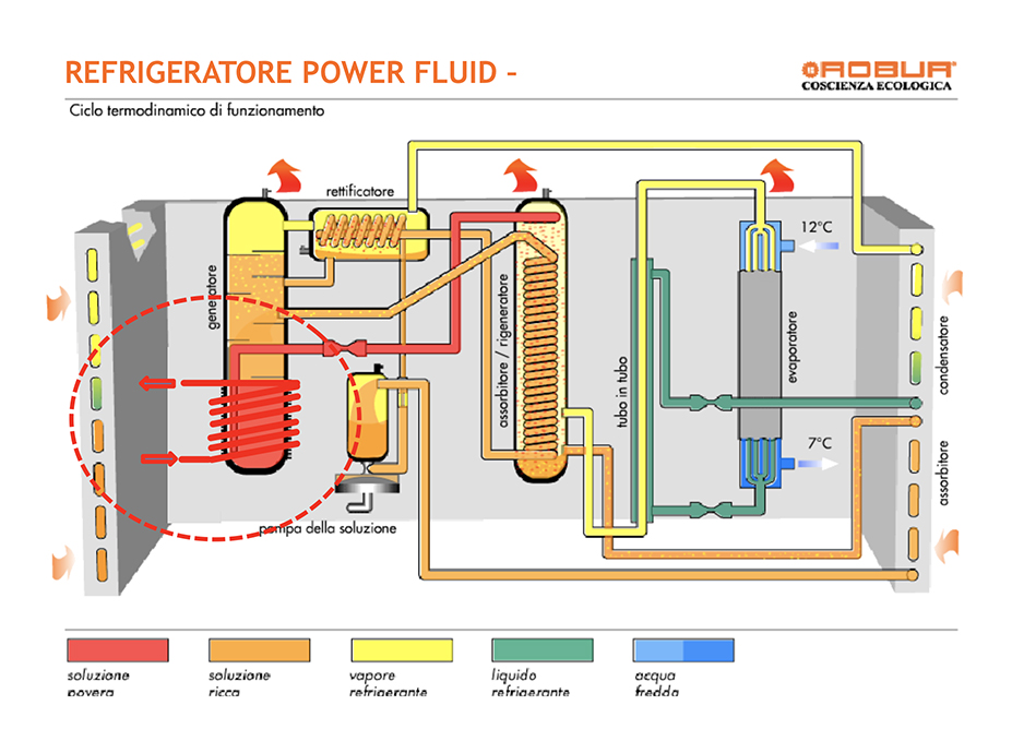
The thermodynamic cycle employs a solution of water and ammonia, in a hermetic closed circuit that avoids refill, substitution and disposal operations. The thermodynamic cycle is triggered by the waste heat flow, heating the generator by mean of a coil, in which diathermic oil or pressurized water are flowing.
Condensation happens in air, without the need of a cooling tower, thus avoiding the related hydraulic circuit and control devices.
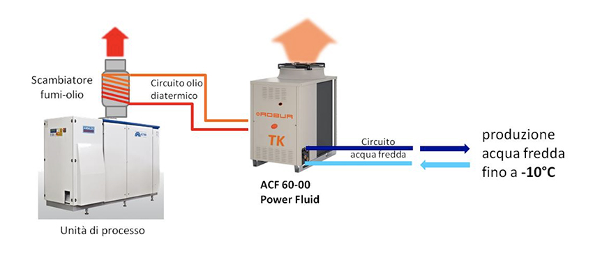
These units enable to produce cold water to be employed for air conditioning, production processes cooling or even for food preservation, being able to supply cold or chilled water down to -10° C.
Advantages of Power Fluid units
Each industrial process involving the presence of waste heat above 200° C and the need of chilling power can benefit from these absorber units, such as metallurgy industry, chemical, glass or cement industry, agrifood and dairy, achieving high energy savings and maximizing the efficiency of the overall production process.
Further advantages offered by Power Fluid units are:
– easy engineering and installation of the plant, not requiring cooling towers and suitable for outdoor installment, with small footprint
– high reliability, thanks to an almost static refrigeration cycle (only two moving parts are employed, including fans) ensuring long life span without efficiency decrease
– wide operating range, in terms of both external air (condensation) and outlet cold water, which can be supplied even at low temperatures of -10° C
– no particular permissions nor authorizations are required, since refrigerants are not employed, replaced by the use of ammonia, a totally natural and eco-friendly refrigerant (near zero ODP and GWP values)
– economically convenient, especially if the unit can be used for many hours/year, being that the chilling power obtained is actually for free
Preliminary feasibility conditions of the recovery plant
Some conditions must finally be verified for a first evaluation of the solution:
– Availability of waste heat at temperatures higher than 220-240° C. This is a mandatory condition to obtain a sufficient transfer fluid able to feed the absorber and effectively trigger the thermodynamic cycle
– concomitant presence of heat recovery and need of chilling power. The cooling energy supplied by the absorber is always subjected to the presence of waste heat to feed it. When chilling power production exceeds the cooling need it is also possible to store it, but it involves higher investments in the chiller circuit to be carefully evaluated
– Estimation of operating hours/chilling power required in order to calculate the ROI. The overall amount of chilling power produced will cover the costs of the plant, so that the higher the indicator is, the shorter will be the ROI.
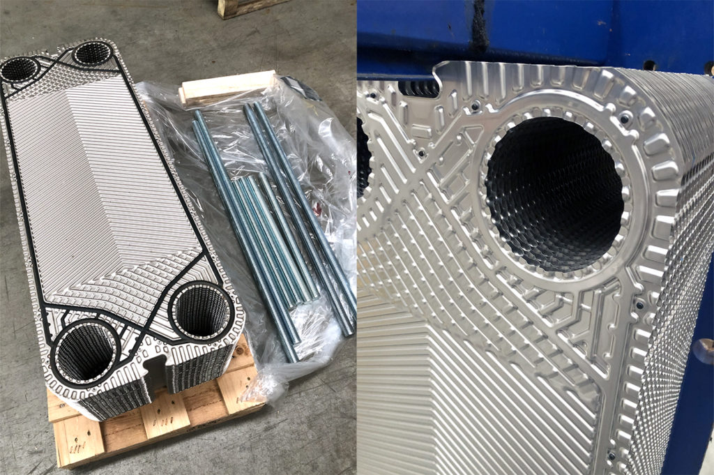
 Having it all be done, the exchanger has been closed respecting the tightening standard settings, then proceeding with pressure test of both circuits separately. A data plate has been put on the machinery, updated with the date of the regeneration intervention and a serial number for future traceability of spare parts employed (gaskets, nozzle liners). The revamped exchanger was finally ready to be re-installed.