 Il fouling factor o fattore di sporcamento, è un fattore determinante per il dimensionamento degli scambiatori di calore a piastre.Negli scambiatori di calore a fascio tubiero, i valori del fattore di sporcamento da tenere in considerazione, sono dettati dalle regole di dimensionamento degli scambiatori stessi (Tema o altro…).Negli scambiatori di calore a piastre, per via del loro tipico funzionamento, tali valori si discostano di parecchio da quelli tipici degli scambiatori a fascio tubiero…addirittura utilizzare valori “da fascio tubiero” nel progetto di “un piastre”, può portare a risultati negativi, per via del maggiore sporcamento indotto dalla bassa velocità che si viene a creare nei canali.Vista la criticità di questo argomento, preferisco inserire un articolo con testo integrale in inglese, in quanto la traduzione sarebbe passibile di interpretazioni “poco chiare” o “poco chiarificabili”.
1.1.1. Fouling Source: Excerpt of VDI-Wärmeatlas, 9. edition 2002, Od 1 – Od 11
Introduction
Nearly every heat transfer media includes a certain amount of dissolved, suspended or growth supporting materials. All these can enable a more or less stable layer on the surface of the heat exchanging material.
Most of these layers have really small heat conductivity.
The low heat conductivity of the layers leads to a further heat transfer resistance.
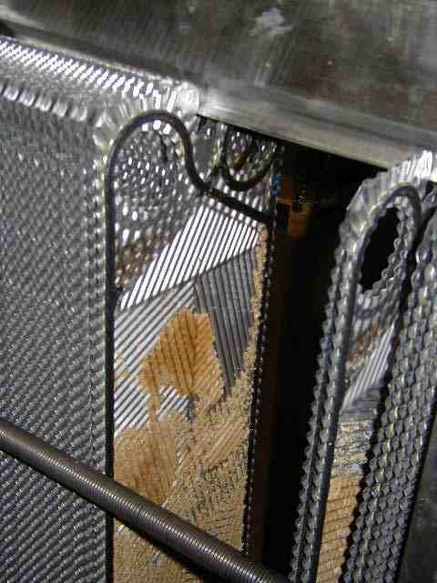
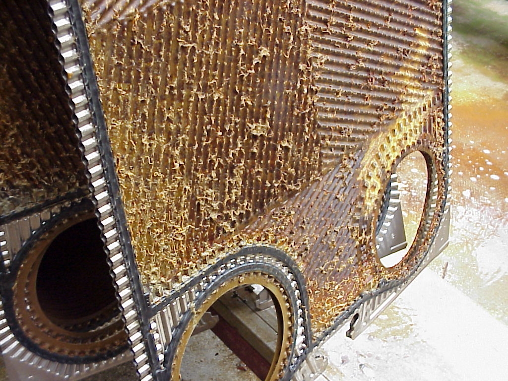
The process of the growing deposits is called fouling in common language use.
- Fouling and Sedimentation can have the following reasons
- Crystallisation fouling: Precipitation and deposition of salts. Example: Best example for this behaviour is heating of water at temperature above 45°C to 55°C carbonates crystallize and will build up a film on the heat transfer area.
- Particle fouling: Sedimentation of sand or mud on surfaces with any kind of slope.
- Reaction fouling: Formation of deposits caused by chemical reactions on the heat transfer surface. Example: Heating protein containing products like milk will lead at certain temperatures to a burning of these proteins on the hot surface.
- Corrosion fouling: Formation of an oxide layer on the on the heating surface.The thermal transfer resistance is very low, because the oxide surfaces are very thin and the heat conductivity is relative high. The problem of the corrosion fouling is the supporting trait of other kinds of fouling.
- Biological fouling: Increase of algae, mussels, bacteria or others on the heat transfer surface. Example: Mostly related when river or sea water is used as cooling water.
Depending on the design fouling can be avoided or minimized by reducing hot water temperature, increasing velocity or using meshes or filters.
All these measures are not in the responsibility of the heat exchanger supplier.
Practical design of heat exchangers
Plate heat exchangers are often an economical solution if corrosion resistant materials are required. The deposit forming is usually considered by calculating an excess heat transfer surface. The size of the excess surface margin must be as high as the heat exchanger can be used a reasonable time.
TEMA shell & tube heat exchanger
For the calculation of the initial excess size of shell & tube heat exchanger is the guideline with the fouling resistance terms of the Tubular Exchanger Manufacturer’s Association (TEMA) useful.
Other heat exchanger constructions
Plate Heat exchanger Caused by a higher turbulence plate heat exchangers leans to a lower deposit forming as shell & tube heat exchangers.
An examination of the deposit forming in plate heat exchangers and shell & tube heat exchangers with produced cooling water has the result that a plate heat exchanger with a velocity of 0.45 m /s has only one third of the deposit forming of a shell & tube heat exchanger with a velocity of 1.34 m/s. An examination with black liquor (67% solids content) shows a deposit forming in a double tube heat exchanger during 2 hours.
The parallel running plate heat exchanger was free of deposits after 24 hours. Nevertheless the heat transfer coefficient of plate heat exchangers e.g. in the dairy industry went down around 30% during one day.
Caused by hygienic reasons and the resulting recurrent cleaning cycles is fouling in this kind of industry a secondary problem.
Typical heat transfer coefficients of plate heat exchangers are around 6000 W/m²K compared with this are the heat transfer coefficients of shell and tube heat exchangers around 1500 W/m²K. Caused by these different heat transfer coefficients it is not advisable to calculate plate heat exchangers with the fouling resistance of shell and tube heat exchangers. With an exemplary fouling resistance of 0,15m²K/kW is the surface margin of a shell and tube heat exchanger around 22%. For the same example the surface margin of a plate heat exchanger will be 90%.
There are different recommendations for the fouling resistance of plate heat exchangers. In general the choice of the fouling resistance should result an over sizing of the plate heat exchanger below 25%.